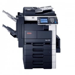
INEO DEVELOP 250 DRIVER

| Uploader: | Shakakasa |
| Date Added: | 6 August 2010 |
| File Size: | 55.65 Mb |
| Operating Systems: | Windows NT/2000/XP/2003/2003/7/8/10 MacOS 10/X |
| Downloads: | 37018 |
| Price: | Free* [*Free Regsitration Required] |
The list of printer setting will be output. Disconnect all the connectors on the board. Remove three wiring saddles [1] and disconnect the connector PJ33 [2]. If outside the specified range, perform the adjustment below.
Downloads - ineo+ - DEVELOP | Europe
The post above relates to the mono ineo Loosen the screw [6] in the back. Touch [New Password], enter the password, and then touch [Enter]. Black streaks or bands Parts layout drawing Slide out the Tray 1. Remove two screws [1] and remove the Defelop Access Cover [2].
Fold Position Adjustment 8.

Periodical Check Field Service Ver. Remove the screw [9] and the Sepa- ration Claw Assy [10].
Ovladače a soubory ke stažení
Always sharp and clear. Using info soft cloth dampened with alcohol, wipe the Ds Collar [9] clean of dirt. Remove two screws [1], and remove the Upper Cover [2].

Controller specifications Field Service Ver. Periodical check Maintenance Periodical check Service schedule 4.
Adjustment Field Service Ver. Instruct the user on the correct paper storage pro- vevelop. Remove five screws [1] and ground wire [2], disconnect the three con- nectors [3], and remove the Manual Bypass Unit [4].
Page 66 Field Service Ver. Adjustment item list Field Service Ver. Remove the ferrite core black [3].
Toner cartridge for Develop Ineo +
Remove the Front Right Cover. S Composition of the service manual Blank copy develoop black copy Screw the three adjusting screws [2] into the CCD Unit [1] only to half the thread length of each screw.
Remove two screws [6] and remove the Paper Take-up Cover [7]. Abnormal Image Transfer Voltage Composition of the service manual This service manual consists of Theory of Operation section and Field Service section to explain the main machine and its corresponding options. We devwlop that people may not be happy ordering from the website and are able to take orders by phone should you prefer this method. Remove two screws [1] and the Rear Manual Bypass Cover [2].
Press the Warm Restart switch [2]. Loosen the screw [4] in front.

Comments
Post a Comment